
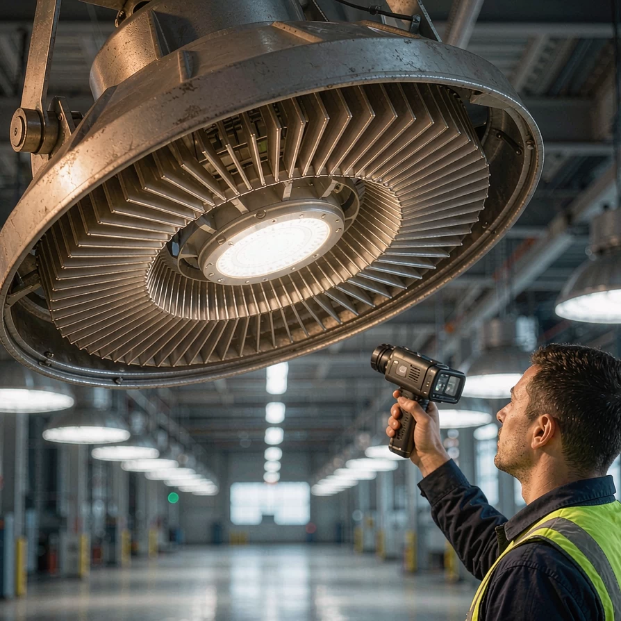
The rated life on the datasheet is an output, not a property
Two 150 W high bays can carry the same LED brand, the same "50,000 h L70" claim and the same lumen package — and one can be visibly dimmer within three summers while the other runs for a decade. The difference is almost never the chip. It is how fast the fixture moves heat away from the LED junction and away from the driver's capacitors.
Thermal management is the least visible part of a luminaire, the hardest to judge from a photo — and it decides whether the lifetime claim survives contact with a 45°C plant floor. Below: what generates the heat, which single temperature you can check, why the driver usually fails first, and what to write into an RFQ.
The thermal path in one equation
Every LED luminaire obeys the same relationship:
Tj = Ta + P_heat × Rth(total)
- Tj — junction temperature, the temperature at the LED chip itself
- Ta — the local ambient temperature around the fixture, not the weather forecast
- P_heat — the share of input power that turns into heat
- Rth(total) — total thermal resistance from junction to surrounding air, in °C/W
Where the heat actually comes from
An LED at 130 lm/W converts roughly 40% of its electrical input into visible light; the remaining 60% or so leaves as heat inside the housing, before you even count driver losses. A 150 W fixture therefore dissipates on the order of 90 W continuously — and in a sealed IP66 housing or an unventilated ceiling void, that heat has nowhere to go except through the housing.
"Local ambient" matters more than buyers expect. A fixture on an open 8 m bracket sees 35°C air; recessed into an insulated ceiling panel or mounted flat against a sunlit wall, the same fixture can sit in a 50–60°C microclimate that never appears on any weather station.
Rth(total) is a chain of series resistances: LED package to board, board to heatsink through the thermal interface material (TIM), and heatsink to air. Each stage is where value engineering costs years of life — a thin die-cast housing instead of an extruded profile, a grease layer that dries out instead of a phase-change pad, fins so tight that dust bridges them within months.
Tc / Ts: the one temperature you can actually check
You cannot put a probe on an LED junction inside a finished fixture. What you can check is the manufacturer's declared temperature measurement point — the case temperature, usually written Tc or Ts — and compare it with the conditions the LED was tested under.
How LM-80 and TM-21 depend on it
LM-80 is the IES test that measures how an LED package depreciates over time. It runs for a minimum of 6,000 hours (10,000+ preferred) at defined case temperatures — typically 55°C, 85°C and a manufacturer-selected point — at a defined drive current. TM-21 then projects those curves forward, capped at 6× the actual test duration: 6,000 hours of data supports at most a 36,000-hour claim.
The catch: the projection is only valid if the LED inside the finished fixture runs at or below the Ts temperature used in the LM-80 test — verified by an in-situ temperature measurement test (ISTMT) on the complete luminaire. If the fixture's real Ts reaches 90°C and the LM-80 report only goes to 85°C, the "60,000 h" projection is unsupported, and so is any warranty built on it.
The driver usually fails first
LED packages fade gradually; drivers fail. In a well-built driver the pacing component is the aluminium electrolytic capacitor, whose liquid electrolyte evaporates faster as temperature rises. The practical rule is again Arrhenius: every 10°C reduction in operating temperature roughly doubles capacitor life. A capacitor rated 10,000 h at 105°C gives approximately:
| Capacitor core temperature | Projected life |
|---|---|
| 105°C | 10,000 h |
| 95°C | 20,000 h |
| 85°C | 40,000 h |
| 75°C | 80,000 h |
| 65°C | 160,000 h |
The difference between a driver tucked against a hot LED board and one in the cooler zone of the same housing is a factor of four — which is why the same "50,000-hour driver" can die in year three inside a sealed streetlight housing and last fifteen years in a ventilated one. When comparing drivers, ask what core temperature the rated life assumes: the driver choice shapes a fixture's real lifespan more than the LED bin does.
What the safety standard actually tests
Thermal competence is not only about lifetime; it is a safety gate. IEC/EN 60598-1 Clause 12 requires a temperature test on the finished luminaire in a draught-proof enclosure at 25°C ambient, powered at 1.06× rated voltage, run in its worst-case mounting position until thermal steady state. Components carrying a rated Tc value — drivers, capacitors, controlgear — may not exceed Tc + 5 K.
Two things matter to a buyer. The test is done on the complete luminaire, so it catches housing and layout mistakes a driver datasheet cannot; and the report shows measured temperatures and the margin left. A fixture whose driver sits 4 K below its limit passes — but has no headroom for a hot summer, a dusty heatsink or a derated ceiling void. Ask for the report, not just the certificate.
Reading a heatsink like an engineer
You cannot judge thermal design from a photo, but you can ask better questions. The two cheapest indicators are the housing material and the interface:
| Housing material & process | Thermal conductivity | Where it fits |
|---|---|---|
| Extruded 6063-T5 | ~201 W/m·K | High-power high bays, floods, street lights; tall, dense fins |
| Extruded 6061-T6 | ~167 W/m·K | When structural strength matters more than peak conduction |
| Die-cast ADC12 | ~96 W/m·K | Integrated complex housings, sealed designs, 100–150 W class |
| Anodised finish (surface) | emissivity ~0.05 → ~0.85 | Raises the radiative share, most useful on outdoor fixtures |
Extruded 6063 conducts roughly twice as well as die-cast ADC12 and allows taller, denser fins, which is why serious 200 W+ industrial fixtures trend towards extruded profiles. Die-cast housings still make sense where geometry, sealing and unit cost dominate — but then the LED load and driver placement must be designed around that limitation. (Anodising raises the radiative share of cooling; conduction through the metal still sets the junction temperature.)
The interface matters just as much: silicone grease is cheap but pumps out and dries over years of thermal cycling, while phase-change pads hold contact resistance far better. And fins closer than roughly 6 mm can choke natural convection in dusty plants within a season — one more reason to match the IP rating to the real environment rather than default to the highest number.
A worked screening example
Take a 150 W, 130 lm/W industrial fixture in a 40°C plant hall. Heat to dissipate: ≈ 90 W (about 60% of input power).
- Good design, Rth = 0.35 °C/W: ΔT ≈ 32 K → junction ≈ 72°C. Comfortable: the LED runs below every LM-80 test condition and the driver's capacitors stay in their long-life zone.
- Value-engineered design, Rth = 0.55 °C/W: ΔT ≈ 50 K → junction ≈ 90°C. The LED solder point now exceeds the 85°C LM-80 condition, so the datasheet lifetime projection no longer applies — and the driver capacitors, running about 20 K hotter, age roughly four times faster.
Same lumen package, same LED brand, same warranty text — two very different fixtures. The screening needs only a declared Rth or an in-situ Ts report.
Five lines to put in your next RFQ
- Declare the Ts/Tc measurement point and provide the in-situ temperature measurement test (ISTMT) report for the finished luminaire.
- Provide the LED LM-80 report (duration, Ts temperatures, drive current); state the fixture's operating Ts and confirm it is at or below the tested condition.
- State the driver's electrolytic capacitor rated temperature and life, and the capacitor core temperature at rated load; a life-versus-temperature curve beats a single MTBF figure.
- State the housing material and process (extruded 6063-T5 vs die-cast ADC12), the TIM type, and the surface treatment.
- Provide the IEC/EN 60598-1 Clause 12 temperature test report at 1.06× rated voltage, with measured temperatures against every rated limit and the declared rated ambient ta for the actual mounting orientation.
The takeaway
Thermal management is where LED luminaire quality actually lives. The chip is a commodity; the housing, the interface and the driver layout are where suppliers quietly save money — and where your maintenance budget quietly disappears. Ask for temperatures, not hours: a supplier who can produce an in-situ Ts report, 10,000-hour LM-80 data and a driver capacitor life curve has told you more than any 50,000-hour claim ever will.
At Solarix Lighting (Guangzhou Xuyuan Lighting Technology), thermal design is a specification item, not a marketing line. Our industrial and outdoor ranges — from UFO high bay lights to modular street lights — use declared Ts points, LM-80-backed LED packages and drivers selected for their capacitor life curves, proven across metro stations, airport terminals and municipal road projects. Send us your mounting orientation, ambient temperature and daily burn hours, and we will return the thermal numbers for your exact application.