
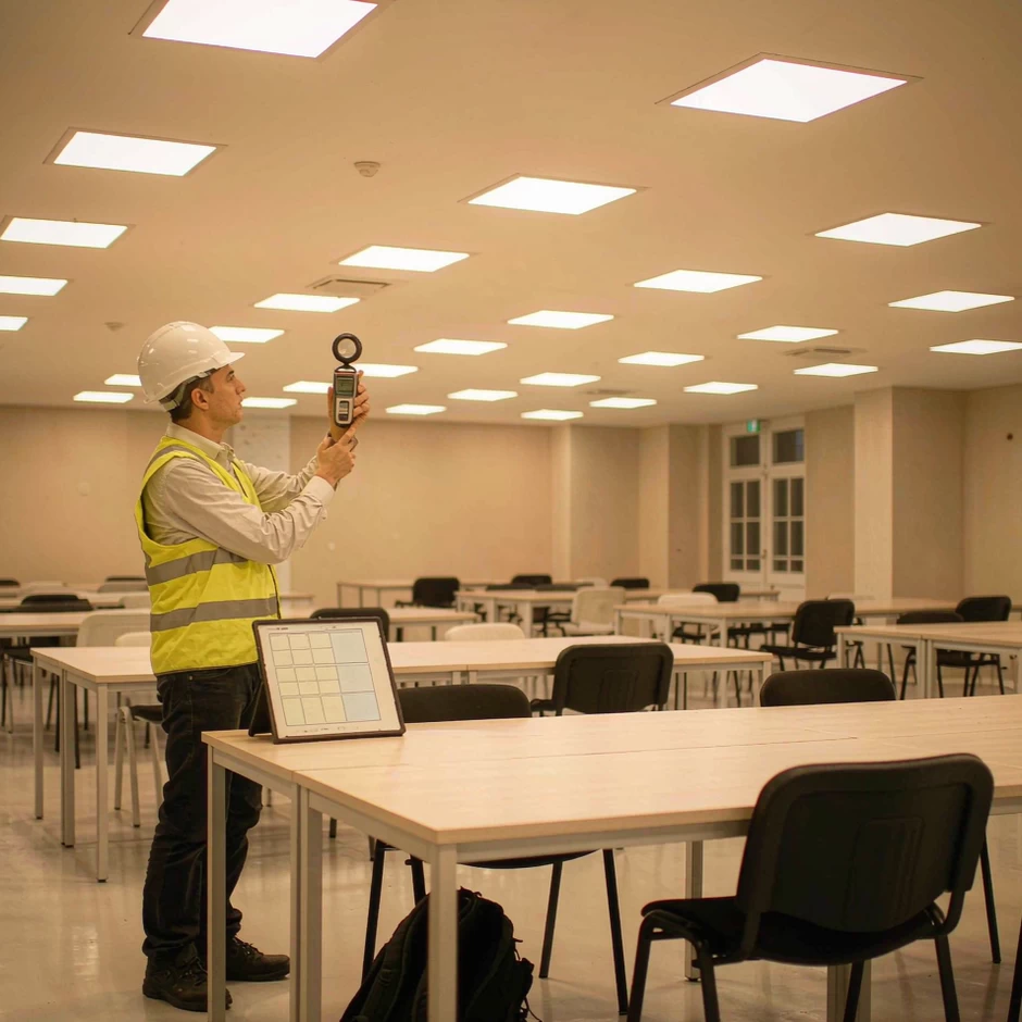
1. Why Handover Is Where LED Projects Actually Fail
Four problems cause most failed sign-offs, and none of them is an optical design error. First, the maintenance factor: a design targets maintained illuminance — the level the installation must still deliver years later — while a new installation always reads higher. Compare day one against the design value and almost anything passes, then it fails in year three. Second, controls left at factory default: no DALI addresses, no sensor groups, no scenes. Third, colour inconsistency — mixed CCT bins show as pink and green patches. Fourth, missing paperwork: no IES files for the delivered model, no LM-79, no emergency test log. The fix is cheap — agree the commissioning method in the contract before installation starts.
2. Get the Measurement Conditions Right First
Let the installation stabilise
LED output varies with junction temperature, so a cold luminaire reads brighter than a hot one. Run the installation at full output for 30–60 minutes before the first reading and record the ambient temperature. Laboratory testing goes further — 100-hour seasoning is standard — but on site, thermal equilibrium is what matters.
Take daylight out of the equation
A lux meter cannot separate daylight from artificial light. Measure after dark or with blinds closed. Where that is impossible, use the subtraction method: measure lights off, then on, and take the difference at each point.
Use a calibrated meter and the correct plane
An uncalibrated meter can be 10–15% off — the same size as the tolerance you are testing. Log the meter model, serial and calibration date, and measure at the plane in the specification: 0.75 m for desk tasks, 0.85 m for a workbench, floor level for warehouse aisles.
3. Build the Illuminance Grid the Way the Standard Does
Picking a few "representative" points causes more arguments than anything else. EN 12464-1:2021 defines the grid explicitly. The maximum grid cell size is:
p = 0.2 × 5^log10(d) (p ≤ 10 m), where d is the longer dimension of the area in metres.
| Longer side d (m) | Max grid spacing p (m) | Minimum points per side |
|---|---|---|
| 1 | 0.20 | 5 |
| 5 | 0.60 | 8 |
| 10 | 1.00 | 10 |
| 25 | 2.00 | 12 |
| 50 | 3.00 | 17 |
| 100 | 5.00 | 20 |
Three details matter. Read at the centre of each cell, not the corners. And do not let grid spacing coincide with luminaire spacing — if it does, you measure the pattern instead of the room. A border band of 0.5 m, or 15% of the smaller dimension (whichever is smaller), may be excluded unless a task area sits inside it.
On large projects, sample a representative set of rooms plus all corridors, stairs and escape routes, and archive the drawing so the sample can be repeated. For the design side, see how many LED fixtures a space actually needs.
4. Uniformity and Maintained Value Are the Numbers That Matter
Average illuminance is the number everyone quotes and the least useful one. Uniformity is U0 = E_min / E_avg. EN 12464-1:2021 requires U0 ≥ 0.40 in the immediate surrounding band and ≥ 0.10 on walls and ceiling; for office writing, typing and data processing the row reads 500 lx, UGRL 19, U0 0.60, Ra 80. A room averaging 520 lx with a U0 of 0.42 has bright pools and dark corners — occupants will complain.
Then apply the maintenance factor. A 500 lx maintained target at a factor of 0.80 means the design was built around roughly 625 lx initial. Measuring 505 lx on day one means the installation drops below target within a couple of years — so check the LM-80 and TM-21 data behind the depreciation assumption, as set out in our L70 and lumen maintenance guide. And put U0, the maintenance factor and the measurement window into the contract — not just the average lux figure.
5. The Things a Lux Meter Cannot See
Colour consistency. Look at the ceiling from a shallow angle. Mixed CCT bins show as pink and green patches even when every datasheet says 4000K. Specify 3–5 SDCM binning and check delivered batches; metrics are explained in our colour quality guide.
Glare. UGR is calculated from a photometric file, not measured on site. Sit in the working position and look along the sight line: if you can see the emitting surface above the shielding angle, the layout will feel uncomfortable.
Flicker at dimmed levels. Test at 100%, 50% and minimum. A dead zone or visible flicker at the bottom of the range is almost always a driver–control mismatch, not a fixture defect; a phone-based flicker app catches it. See our flicker and blue light article.
Aiming. Floodlights, asymmetric high bays, wall washers and road luminaires must be checked after dark. A 5° error on a road luminaire moves the beam off the carriageway. See our roadway distribution guide.
6. Commission the Controls, Not Just the Fixtures
Treat control commissioning as a separate signed milestone, not an afterthought — "the controls were not in scope" is one of the classic handover disputes.
For DALI, every control gear on a bus gets a short address (up to 64 per bus power supply), then groups and scenes. Verify that the address list matches the as-built drawing, that no two devices share an address after a replacement, and that every scene recalls. For 0–10V or phase-cut systems, run the full ramp 100% → minimum → 100% and watch for drop-out, pop-on and non-linearity.
Walk-test sensors for detection zones and hold time, and check that a daylight sensor is not fighting the setpoint — a system that hunts every few minutes gets switched off manually. Emergency lighting needs its own logged record: a short functional test at handover plus a full-duration discharge test. See our emergency lighting buying guide.
7. Electrical, Thermal and Enclosure Spot Checks
At the distribution board, clamp each lighting circuit and compare with the design load. If a breaker trips at switch-on but the running current is fine, the cause is inrush current, not overload — see our load calculation article.
Use an infrared thermometer or thermal camera on a sample of housings. A fixture running 15–20°C hotter than its neighbours usually has a thermal interface problem or a driver beyond its rated case temperature.
Outdoors and in tunnels, check gland tightness, gasket seating, drain-hole orientation and earth bonding. Most ingress failures are installation failures, not product failures — see our IP rating guide.
8. The Document Package to Demand Before Sign-Off
| Document | What to check |
|---|---|
| Photometric files (.ies / .ldt) | Model code matches exactly what was delivered |
| LM-79 report | Measured lumens, efficacy, CCT, CRI, PF, THD |
| LM-80 + TM-21 | Lifetime claim and the temperature it was projected at |
| Certificates | CE / CB / UL / ETL / DLC / PSE, per destination market |
| As-built layout | Circuit schedule plus DALI address list |
| Measurement report | Grid drawing, meter serial, calibration date, ambient temperature |
| Emergency test log | Functional and full-duration results |
| Warranty and spares | Terms in writing, 2–5% critical spares |
9. Where Solarix Fits
Solarix Lighting (Guangzhou Xuyuan Lighting Technology Co., Ltd.) manufactures commercial and indoor luminaires, outdoor and industrial fixtures, downlights and LED panel lights, with references across 20+ metro and rail transit stations, airport terminals and municipal road schemes. We hold CE, CCC, PSE and RoHS certification, and every quotation can include full photometric files, LM-79 and LM-80/TM-21 data, and a commissioning checklist matched to your specification.
Send us your room layout or road section and the target standard, and we will return a lighting calculation, the IES files behind it, and a point-by-point acceptance checklist your contractor can work from.