
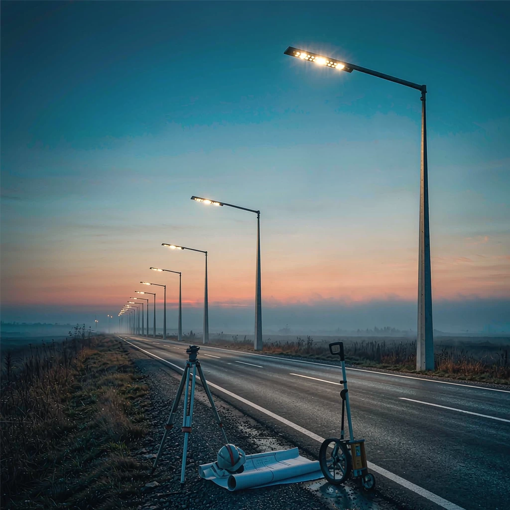
LED street light pole height and spacing appear on almost every road lighting drawing — and they are also the two numbers most often copied from the previous project without being checked. Get the geometry wrong and no amount of lumen output, driver quality or optical tuning will rescue the installation: light pools unevenly, dark patches open between poles, and the design fails its uniformity target even though average illuminance looks fine on paper.
Mounting height determines how wide one luminaire can throw usable light and how much glare road users experience. Spacing determines how well those pools overlap into a continuous band along the carriageway. The two are geometrically coupled — raise the pole and you can usually widen spacing; tighten spacing and you may work with a lower mast — but both are constrained by road width, lane count, classification, arrangement, structural limits and local rules.
Written for B2B buyers, contractors and consultants specifying road lighting, this guide explains what sits behind those two numbers, how road classes translate into height bands, how spacing is verified, where the standard rhythm has to break, and how to write the requirement into an RFQ so competing bids compare like for like.
Why Height and Spacing Decide Whether a Design Passes
In the companion LED Street Light Buying Guide, most attention goes to the fixture: lumen package, efficacy, IP rating, surge protection, driver quality. Those choices matter, but they assume the fixture is mounted somewhere sensible. A 150 W luminaire on too short a pole produces a small, harsh pool with a black gap before the next one; the same luminaire at the right height throws a wider, softer pool that blends into its neighbours.
Three variables that move together
- Raise the height and one luminaire covers a larger footprint, so spacing can grow — but surface illuminance falls, so more lumens may be needed to hold the same level.
- Widen the spacing and you buy fewer poles and fewer maintenance points — until the pools stop overlapping and uniformity collapses.
- Add output and you can lift illuminance or buy wider spacing — at higher energy cost and typically more glare if height is not adjusted too.
Quoting “a 120 W street light” without declaring height and spacing produces a number nobody can judge: identical wattages can be generous or inadequate depending entirely on geometry.
Uniformity is what fails first
Average illuminance is easy to hit; distribution along the road is far harder. The uniformity measures used in road lighting practice — average-to-minimum and maximum-to-minimum ratios on the carriageway — are governed largely by how far apart poles sit relative to how high they are. Check the ratio, not just the average.
Start From the Road Classification, Not the Luminaire
Before any height or spacing is fixed, classify the road. Most frameworks — the IES approach used widely in North America (commonly cited as RP-8), the EN 13201 series across much of Europe, and equivalent regional standards — organise roads into classes by traffic volume, speed, user mix and ambient conditions, each carrying target illuminance, uniformity and glare limits. Confirm which standard and class list the authority enforces before writing the specification. The indicative ranges below orient you; they do not replace the applicable requirement.
- Trunk roads and arterials: high volume, multi-lane. Typically the tallest conventional masts, commonly 10–14 m, because light must cross several lanes without the near lane becoming a glare source. Spacing often 35–50 m, highly dependent on arrangement and optics.
- Collector and distributor roads: one or two lanes per direction, mixed users. Heights around 8–10 m, spacing commonly 25–40 m.
- Local and residential streets: low speed, narrow carriageway, parked cars. Heights often 6–8 m with 20–30 m spacing; lower masts usually suit the scale better than tall poles spilling light into windows.
- Footways and shared paths: lower targets but stronger glare sensitivity, more interest in vertical illuminance for face recognition, heights typically 4–6 m.
Typical Pole Heights at a Glance
| Application | Typical height | Typical spacing | Dominant constraint |
|---|---|---|---|
| Footpaths, plazas, bike lanes | 4–6 m | 15–25 m | Glare comfort, spill control |
| Residential and local streets | 6–8 m | 20–30 m | Trees, parked cars, light trespass |
| Collector and distributor roads | 8–10 m | 25–40 m | Carriageway width, mixed users |
| Arterials and multi-lane trunk roads | 10–14 m | 35–50 m | Reaching across lanes with few poles |
| Interchanges, yards, ports | 15 m+ (high mast) | Set by mast layout | Structural loading and foundation |
Above roughly 15–18 m the economics and structural requirements change character; that is high-mast territory, covered separately in our guide to high-mast LED lighting for ports, yards and sports areas.
How Far Apart Can Poles Go?
A screening ratio, not a substitute for calculation
A widely used heuristic relates spacing (S) to mounting height (H): for many conventional rows S/H sits around 3:1 to 4:1, higher where the distribution has long throw, lower where light must wrap around obstacles or the uniformity requirement is strict. Pick a height, multiply, and you have a first-pass spacing — then verify it with a photometric calculation on the actual section.
What actually sets the limit
- Optical distribution. Long-throw optics bridge a bigger gap than symmetric ones, so spacing must never be quoted before the distribution is chosen (see IESNA roadway distribution types).
- Road width and overhang. Light landing outside the carriageway contributes nothing to uniformity; extending the arm beyond the kerb can justify wider spacing on the same mast.
- Tilt. Excessive tilt pushes the peak away from the pole, lifting mid-span illuminance while darkening the area beneath the fixture.
- Maintenance factor. Verify with maintained values that allow for lumen depreciation and dirt, not day-one figures — see L70 and lumen maintenance.
Where canopies are heavy, curves sharp, or wet-surface reflectance matters, the answer is often closer poles rather than bigger luminaires.
Arrangement Matters as Much as the Number
The same spacing behaves differently depending on where poles sit. Always specify arrangement alongside spacing:
- Single-sided: cheapest and simplest to wire and maintain; best on narrower carriageways, with uniformity falling off across the far lane as the road widens.
- Staggered: poles alternate sides so pools interleave, improving uniformity across the width.
- Opposite: paired poles facing each other; the usual answer for wider roads, at higher installed cost.
- Twin-arm: one central or median pole carrying two heads; roughly halves foundations on divided roads.
- Median: efficient on divided highways, but plan maintenance access and impact protection carefully.
Optics: Where Geometry Meets Output
Our N Series Slim LED Street Light is published with Type I, Type II, Type III and wide-road distributions among its options across 30 W to 240 W models. The same 120 W body delivers completely different spacing capability depending on which optical version is ordered — precisely why wattage alone is not a specification. Sanity-check any layout claim by asking for the photometric file: our guide explains how to read an IES or LDT file, and lumens vs lux vs watts resets the fundamentals if needed.
Conflict Areas: Where the Grid Breaks
Straight sections are easy; most real roads have somewhere the regular rhythm must be interrupted.
- Intersections: conflicting traffic streams and signal heads raise the requirement; treat each junction as its own entity and expect extra heads or relocated poles.
- Roundabouts: circulating carriageway, island and entries each need attention, often combining standard masts on approaches with lower equipment inside.
- Pedestrian crossings: usually need vertical illuminance so a person facing traffic is visible; fixtures are commonly placed on the approach side rather than over the crossing itself.
- Curves: poles normally sit on the outside of the curve and spacing generally tightens — never carry straight-section spacing through unchecked.
Height Is Not Free: Structure, Setback and Access
Taller poles need larger sections, thicker walls, bigger foundations and heavier anchors. Wind load grows sharply with height and with everything mounted on top — bracket arms, twin heads, cameras and small-cell equipment all count toward the effective projected area the foundation must resist. State the wind basis explicitly and have the supplier certify the full configuration, not just the shaft; later additions are a frequent origin of warranty disputes.
Setback from the carriageway edge, vehicle deflection distance, overhead-line clearance and buried services sometimes dictate spacing more decisively than photometrics do. Involve the utility survey early.
Retrofit: Reuse the Poles or Replace Them?
Reuse is realistic when height and spacing already suit the road class, poles pass a structural assessment for the new head’s weight and wind area, foundations are sound, and cabling and access covers are serviceable.
It fails when there is base corrosion, undersized foundations, fatigue cracking, or a replacement head much heavier than the old one — and also where existing spacing is far wider than the design supports, in which case extra heads will not fix uniformity and you need more poles. Either way, budget for commissioning and site acceptance that verifies installed height, arm tilt and measured illuminance.
How to Put This Into an RFQ
Ask every bidder to state, per road class:
- Mounting height above finished surface, arm length and tilt angle.
- Pole spacing centre-to-centre, plus arrangement type.
- Luminaire model, wattage, lumen package and optical distribution.
- Achieved maintained illuminance plus average-to-minimum and maximum-to-minimum uniformity, for carriageway and any adjacent footway.
- Photometric files for the exact variant offered, and a calculation report plotted on your survey drawing.
- Structural basis: wind zone, effective projected area of head and attachments, foundation class and setback assumed.
- Maintenance assumptions: depreciation and dirt factors used in the maintained figures.
That structure turns a wattage spreadsheet into a genuine technical comparison and gives you a documented baseline if the installed result diverges. See also our guide to LED lighting tender and bid documents.
Common Mistakes
- Specifying wattage instead of geometry and measured performance.
- Copying the last project’s spacing onto a road with a different width, class or surface.
- Ignoring uniformity because the average illuminance comfortably passes.
- Mounting too high without checking glare limits or light trespass onto adjacent property.
- Forgetting the maintenance factor, so the scheme meets spec at handover but not in year five.
- Carrying straight-spacing through curves, junctions and crossings, or reusing poles without a structural review.
Road Lighting Products Worth Reviewing
- N Series Slim LED Street Light, 30W–240W — several road optics in one slim body.
- P Series Compact Modular, 50W–300W — modular output steps across road classes.
- S Series Modular, 50W–300W — for larger arterials.
- E Series Mini, 40W–200W — lower profiles for secondary roads.
- Y Series and X Series split solar lights, 30W–60W — for positions without reliable grid supply.
- Browse the full outdoor lighting collection or the complete product catalogue.
Also worth checking before ordering: load calculation and breaker sizing for the final pole count, IP ratings and surge protection for the environment, and market rules such as EU energy label and ecodesign or power density limits in our LPD guide.
Bringing It Together
Pole height and spacing are not inherited drawing notes — they are the decision that determines whether everything else you specify can deliver. Start from the road class and the enforceable standard, pick a height that suits the site’s scale and limits, set spacing so the pools genuinely overlap, then verify by calculation and again after installation. Judge total cost rather than pole count: fewer, taller masts can look cheaper until foundation size, wind certification and maintenance access are priced in.
Planning a road lighting scheme? Share your road widths, lane count, target lighting class and site constraints with the Solarix Lighting team and we will help turn those numbers into a specification your suppliers can quote against on equal terms. Our sourcing checklist is a useful companion from RFQ through to inspection.
Frequently Asked Questions
What spacing-to-height ratio should I use?
A common planning range is roughly 3:1 to 4:1 for conventional rows, though some layouts fall outside it. Use it as a screening filter only; the layout still needs a photometric calculation against the applicable standard and the specific optical distribution.
Can existing pole spacing be kept when retrofitting to LED?
Sometimes. If height and spacing already suit the road class and the new luminaire’s distribution bridges the gap, reuse works. Where existing spacing is much wider than the design supports, additional poles are needed — more heads will not fix uniformity.
Is a taller pole always better on a wide road?
No. Greater height widens reach but lowers surface illuminance, increases wind loading and foundation cost, and can introduce glare or light trespass. Twin-arm or opposite arrangements at moderate height often perform better than one very tall row.
How many lumens are needed per metre of road?
There is no reliable rule of thumb: the answer depends on road width, height, arrangement, surface reflectance and the maintenance factor. Derive output from a photometric layout rather than a per-metre figure — see lumens vs lux vs watts.
Should the lights dim after midnight?
Many authorities specify a curfew dimming profile for light-traffic hours. That is legitimate, but any dimmed state should still respect the lighting class applicable during that period, and the control interface must be chosen at the same time as the luminaire. Confirm the dimming options published for the specific product before ordering.